In the process of getting Holtzapffel No. 1636 up and running safely we almost immediately found ourselves facing the issue of how best to deal with drive belts. When the machine was built in 1838 the only viable options were leather and gut., and the pulleys on the lathe were made elegantly small with a V groove to accommodate those choices.
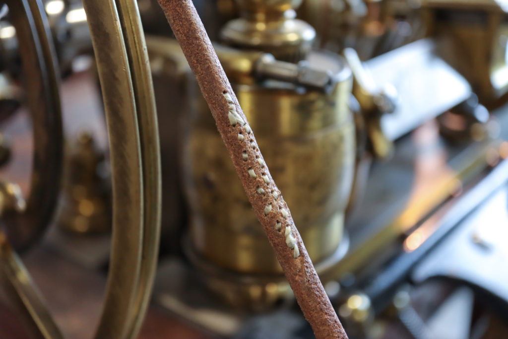
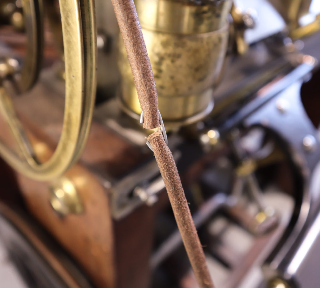
The leather belt that came with the lathe was joined by a staple typical of those used in the past for light duty on sewing machines. When the belt was installed it broke almost immediately as the leather had deteriorated. New leather belting was obtained, cut to length and installed, however, the connecting staple stretched under the tension required to prevent slippage.
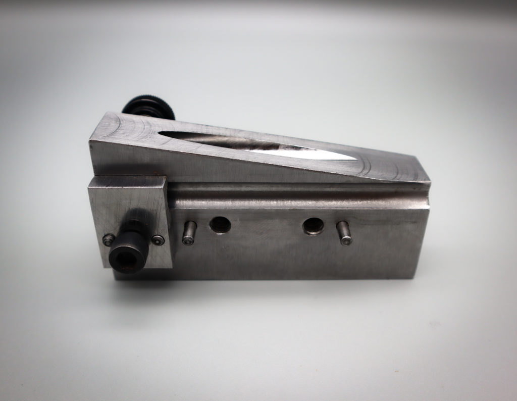
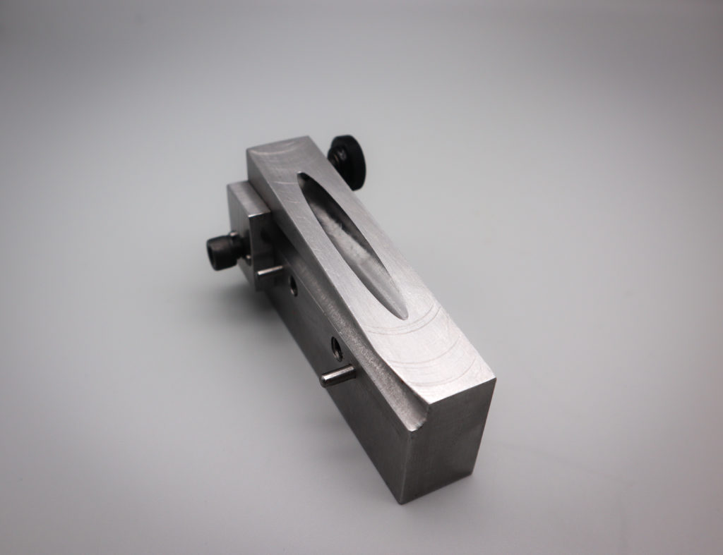
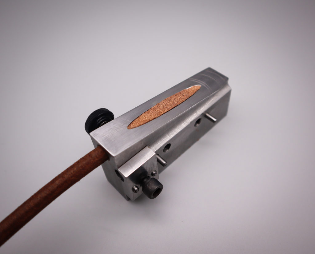
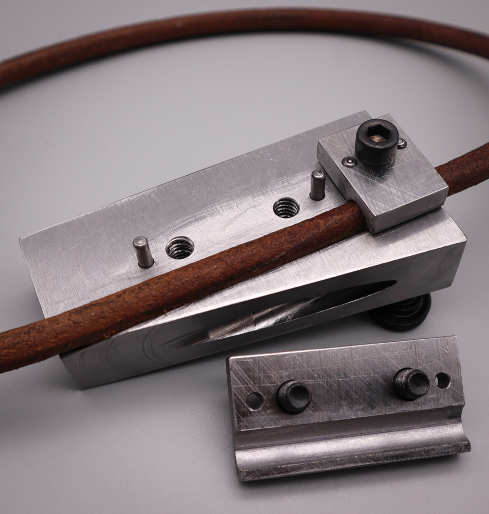
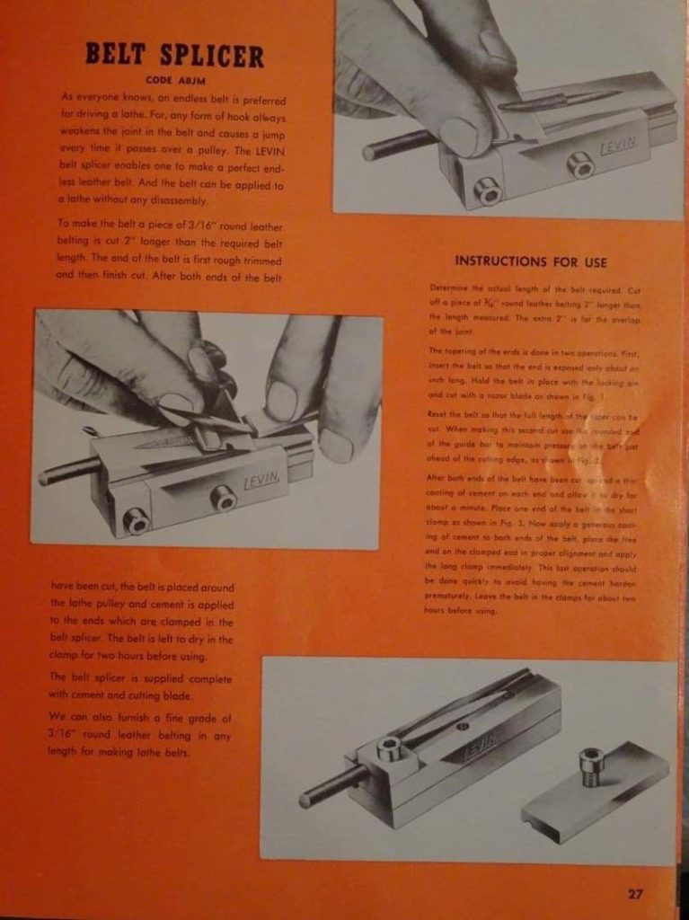
When we mentioned the problem to Frank Dorion, he immediately suggested a tool he’d seen advertised in an old Levin lathe catalogue and had duplicated for use on his own rose engine. He was kind of enough to show up the next time with a “kit” of steel parts ready for machining and a sketch of what needed to be done. Our staff set the Bridgeport milling machine into action and produced the prescribed parts, as having such a tool in the kit of Holtzapffel No. 1636 seemed prudent.
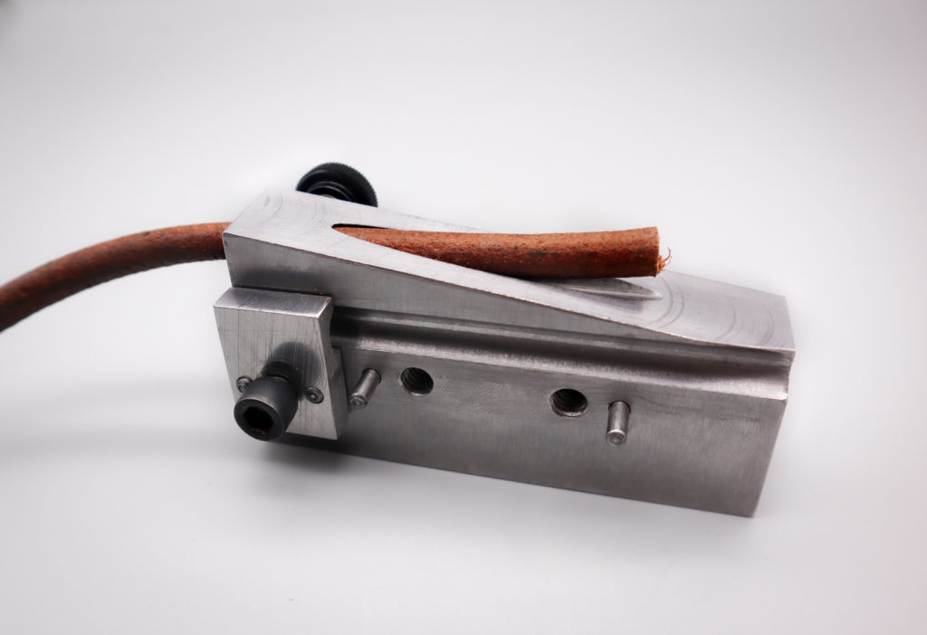
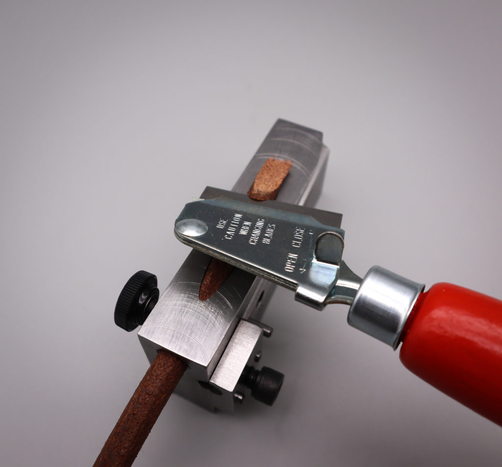
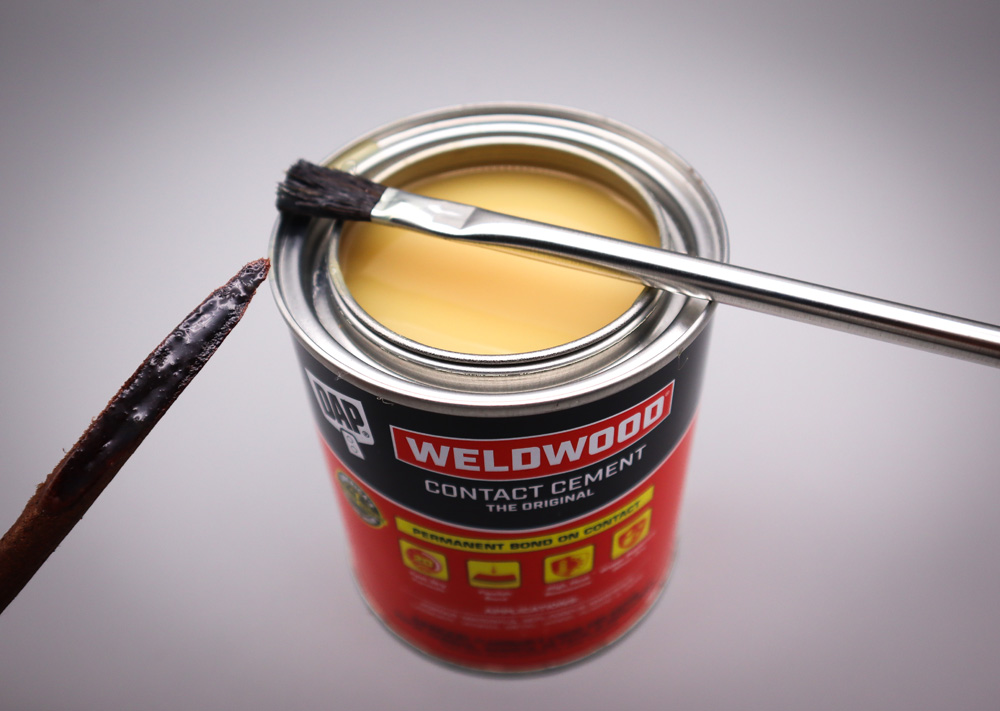
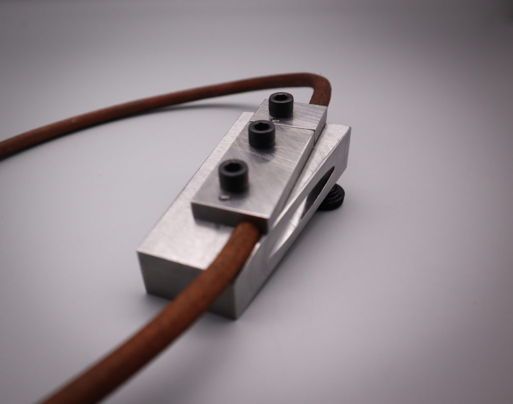
With the splicing tool in hand, we went about making a spliced and sewn belt that would withstand the tension needed to drive the lathe without slipping and be sufficiently durable to take the lathe into the next generation of use.