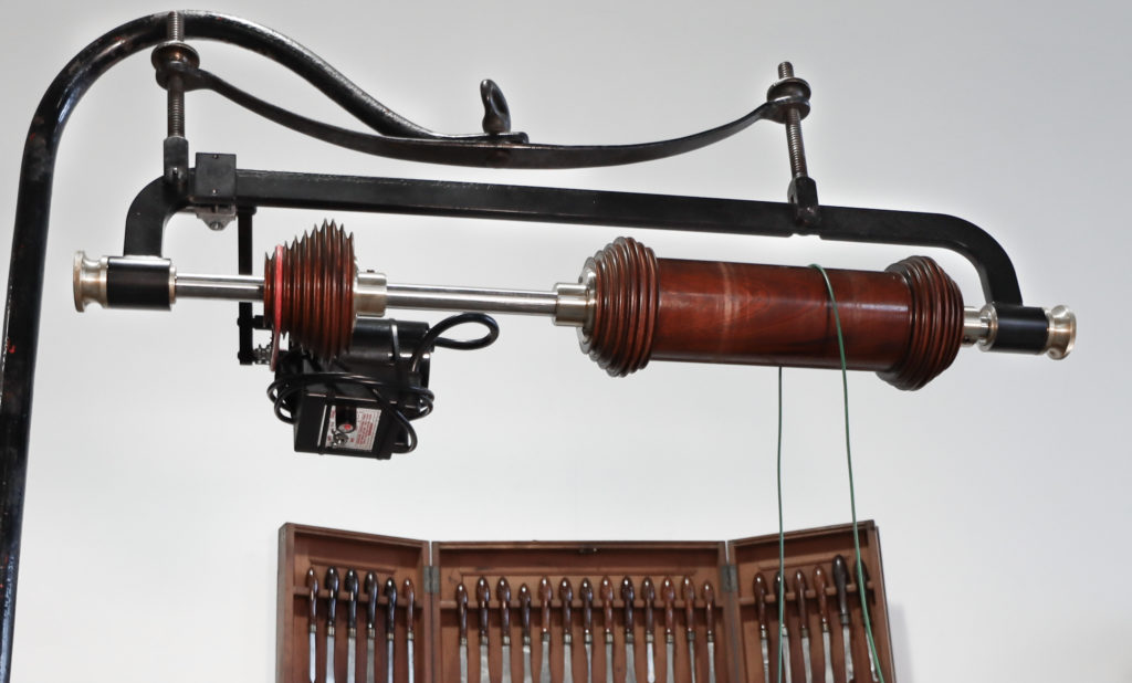
The overhead drive is an essential part of an ornamental turning lathe. It drives the high-speed cutting frames which cut the wood. Unlike conventional wood turning, in ornamental turning the work piece is most often held stationary while the cutting tool rotates. This rotating cutter arrangement is referred to as “live tooling”, as opposed to “fixed tools” which are stationary while cutting. John Holtzapffel introduced live tooling to ornamental turning in the late 18thcentury. An ornamental lathe designed for live tooling is much less complex than the rose engine lathes which previously had been the primary option for ornamental turning. Live tooling revolutionized the practice, and brought the price of the lathes down to where mere gentlemen could afford ornamental turning, a pastime previously reserved only for the wealthy nobility. Holtzapffel’s ornamental turning lathes and those of his subsequent competitors were driven with a treadle connected to a crankshaft with a large flywheel.
There are two major issues regarding the use of a treadle and traditional overhead drive. The first is that of coordination. Ornamental turning is hard enough without the added challenge of standing on one foot treadling the lathe while the operator balances on the other, a posture reminiscent of a pink flamingo. (For a great story about a young man treadling Holtz No. 2157 for Lord Kelvin see “The Workshop” section of our website on that lathe.)
The second issue is one of speed. When the Plumier Foundation’s Holtzapffel lathes were built, ball bearings were not yet an option for the cutting frames, overhead, or treadle. The speeds obtainable with the tapered cone bearings Holtzapffel used were much slower than what is possible today. In the modern world, cutting frames with ball bearings can tolerate speeds of 10,000-20,000 RPM’s. Tapered cone bearings are simply not capable of sustaining such speeds.
A modern DC motor answers the problems of both speed and coordination, completely eliminating the need for the treadle or flywheel as the power source., However, the overhead drive needs to be modified from what it was originally to handle the speeds of a modern electric motor. This modification needs to be done in a way compatible with the look of the old drive to retain the aesthetic of the original machines. Whatever modifications are made have to blend seamlessly with the original design.
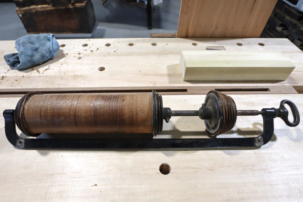
The first order of business we addressed were the pulleys. On the “shepherd’s crook” and “clothesline” type overhead drives usually seen on Holtzapffel lathes, the pulleys are typically made of mahogany and have often suffered from decay and mechanical abuse. The pulley on No. 2195 retained its original pulley in good order, No. 1636 has a replacement is in good condition, and No. 2410 has a pulley that is a mix of original and replaced parts but all are intact and quite serviceable. No. 2157, however, was a completely different story. While the pulleys were original, they were in bad shape with no way to safely operate them. The cracks and splits were deep enough that we decided to simply preserve what was there and make an entirely new set including the brass hubs.
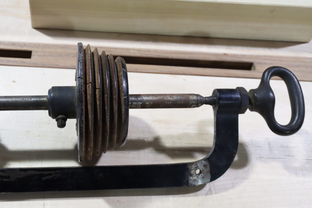
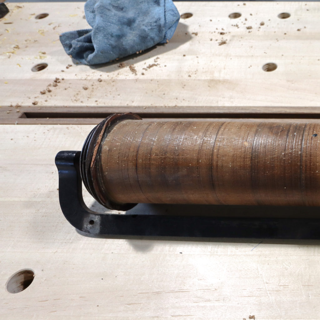
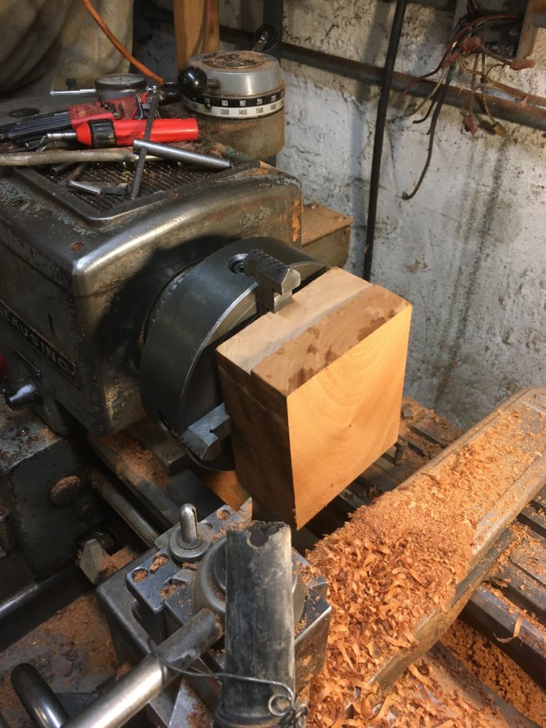
The original pulleys appeared to be made from a single piece of mahogany, but often the wood moves and the pulleys warp. It doesn’t warp enough to affect the aesthetics, but the run out causes a vibration that not only wreaks havoc with the bearings but sends vibrations through the entire lathe. Coupling this with the difficulty of finding a single piece of dry wood thick enough to turn a new pulley, we decided to make the pulley by laminating two pieces. That allowed us to use readily available wood and gain stability as well.
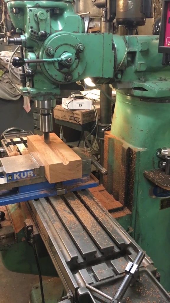
Finding a way to make an accurate hole through a piece that long was the next challenge, but our experience in metal work quickly offered a solution. Once wood was cut to length, the two pieces were sized to match and set into the vise of the milling machine. A ball end mill was used to make a precise semi-circular groove with a 1/2 radius along the length of the boards. Using the milling machine and ball end mill made it possible to sink the groove down precisely 1/2”, creating a 1” round hole when the two boards were mated. The shaft that carries the pulley was to be 7/8” in diameter. However, the pulleys mount to the shaft with brass collars, and the 1/8” clearance provided by the 1” hole in the wood would ensure easy adjustments as only the brass collars with their 7/8” diameter holes would contact the shaft.
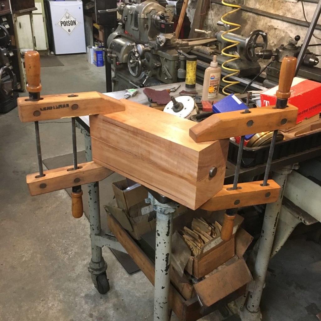
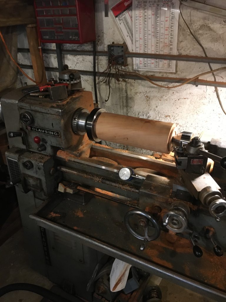
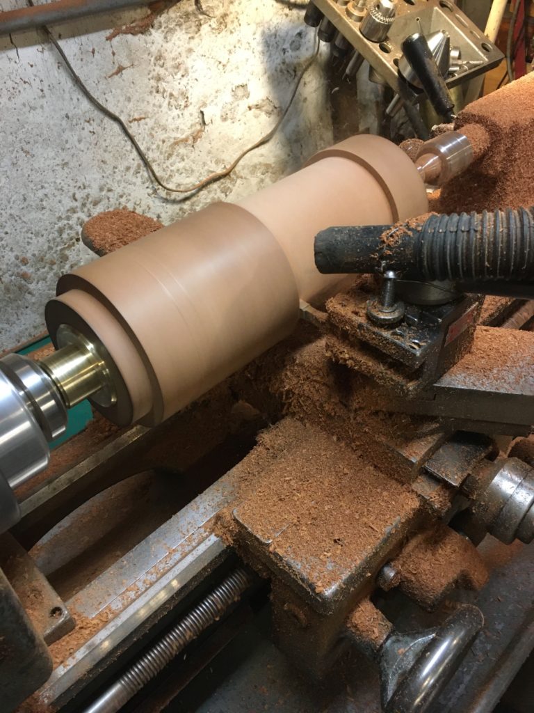
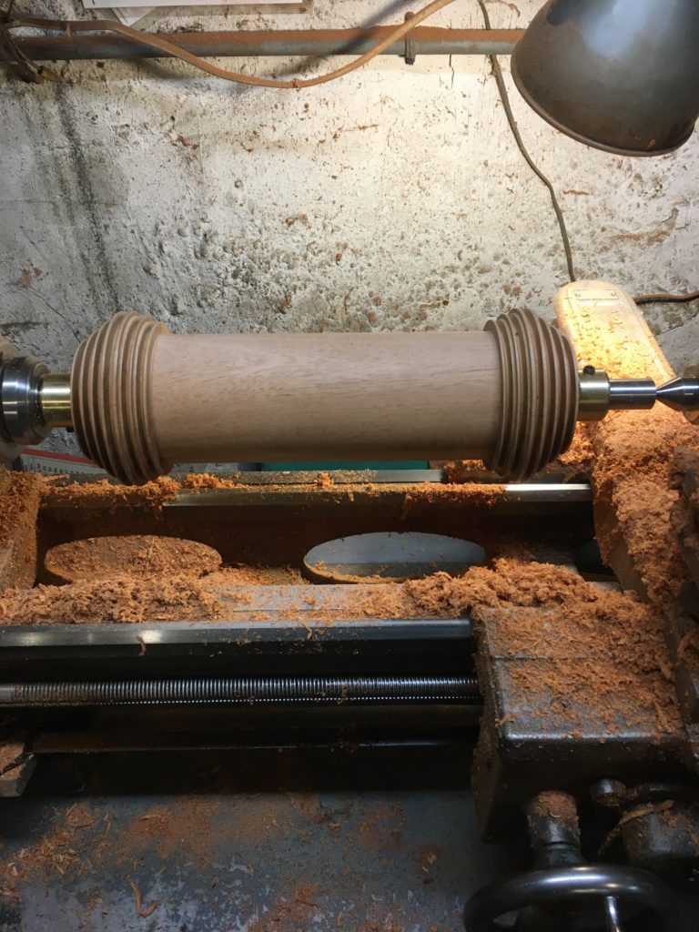
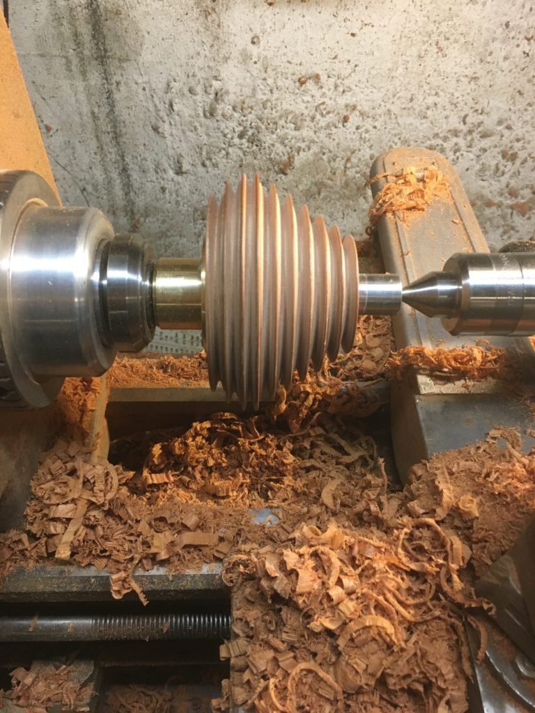
With precisely matching grooves the two pieces were aligned for gluing and clamping simply by putting a piece of 1” bar stock in the grooves before clamping. The piece of bar stock was then mounted between centers in the lathe to align the blank for rough turning, keeping the hole true to the outside diameter.
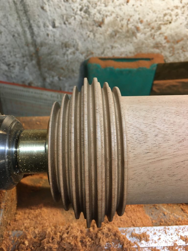
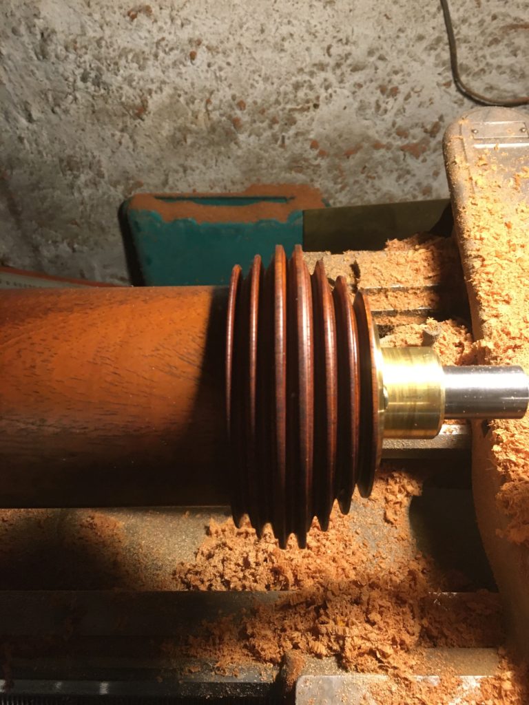
Once round, the piece was easily be chucked into a conventional collet, and the counter bores turned to accurately accept the new brass bushings.
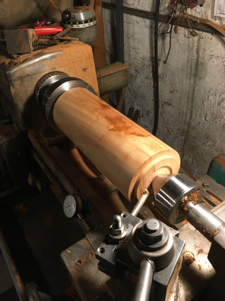
With the counter bores completed, the brass bushings were screwed in place; and for the rest of the project the pulley was held on a bar by the bushings which ensured that it would, at least initially, run true.
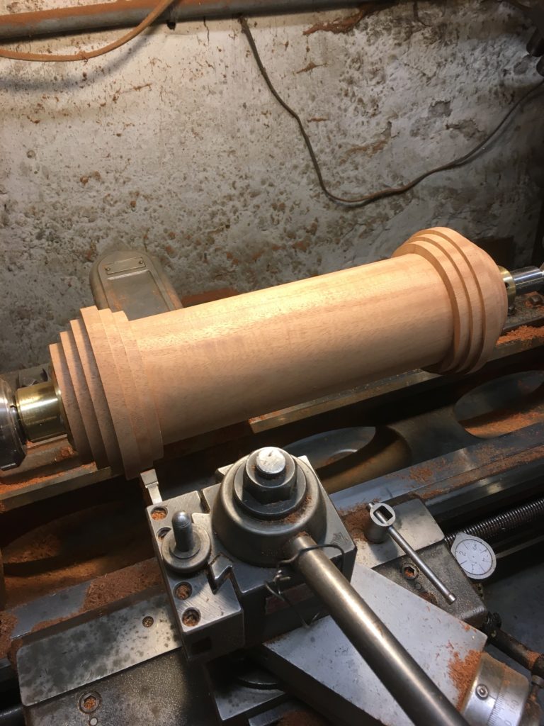
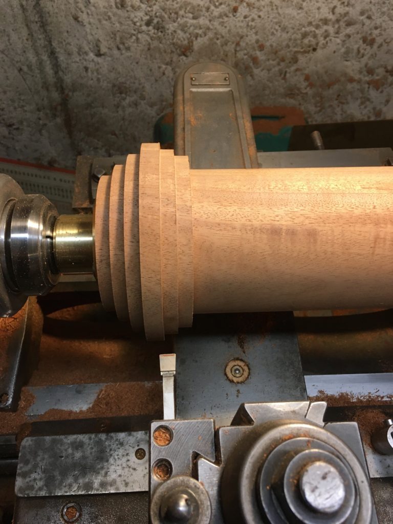
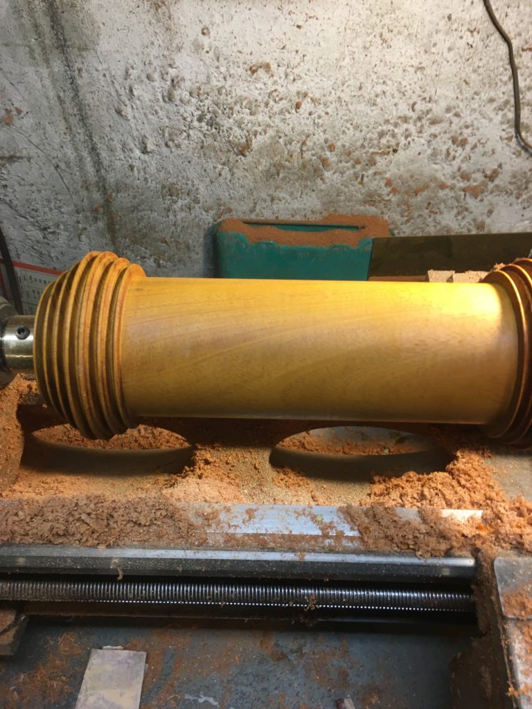
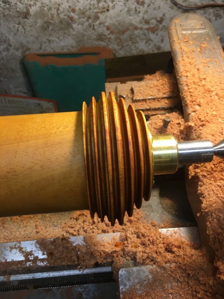
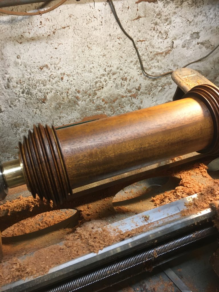
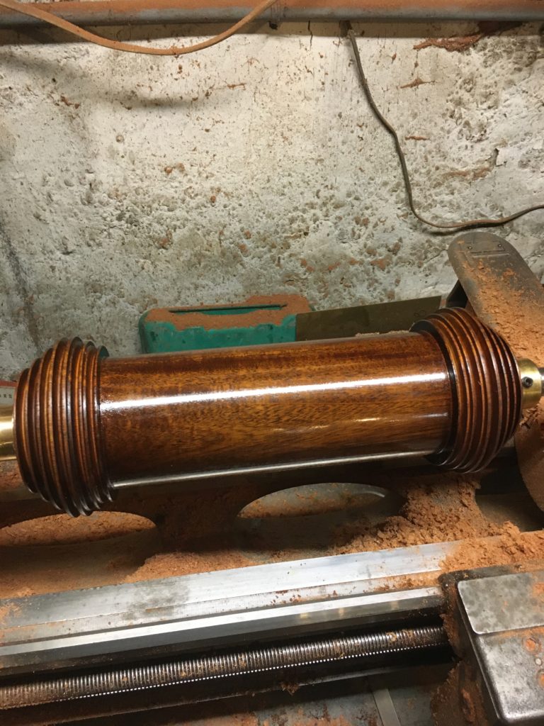
In the end the pulley had the look and feel of the original, and the color matched the lathe. It also ran true and was well balanced. Even the seam between the two pieces of wood blended virtually imperceptibly.
In Part 2 of the blog post we will show how we dealt with the frame in order to add ball bearings in a way that would not be immediately obvious.
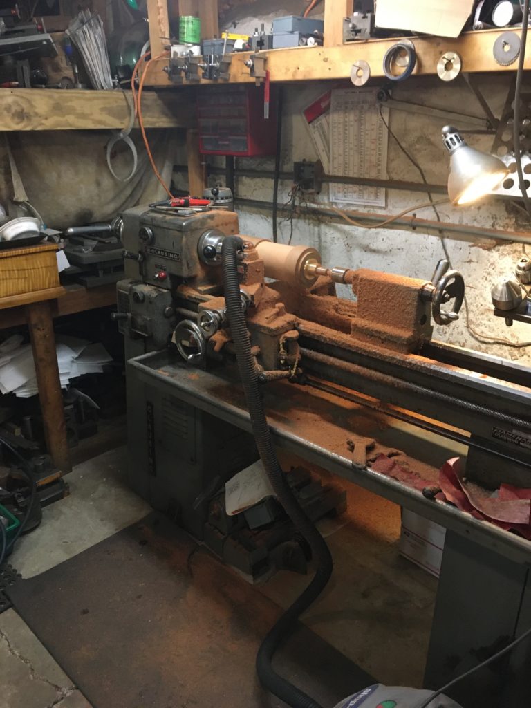
This work was done in David’s shop.