One of the nice things about having a collection of vintage ornamental turning machines that dates from the 1830’s to nearly the end of the 19thcentury is that the advancements in tooling can be seen over this broad range of time. In some ways it’s amazing how similar things remained over such a long period, especially when one considers that this was the golden age of mechanics. The finishes on our earliest Holtzapffels match those of the latest in both style and quality, and in many respects the tooling changed little. Where change is noticeable is in the addition of labor-saving devices.
Holtzapffel no. 2410 was made in 1892. This was a just a few years after George Budd joined the firm and added some interesting new equipment such as the Automatic Driving Device.
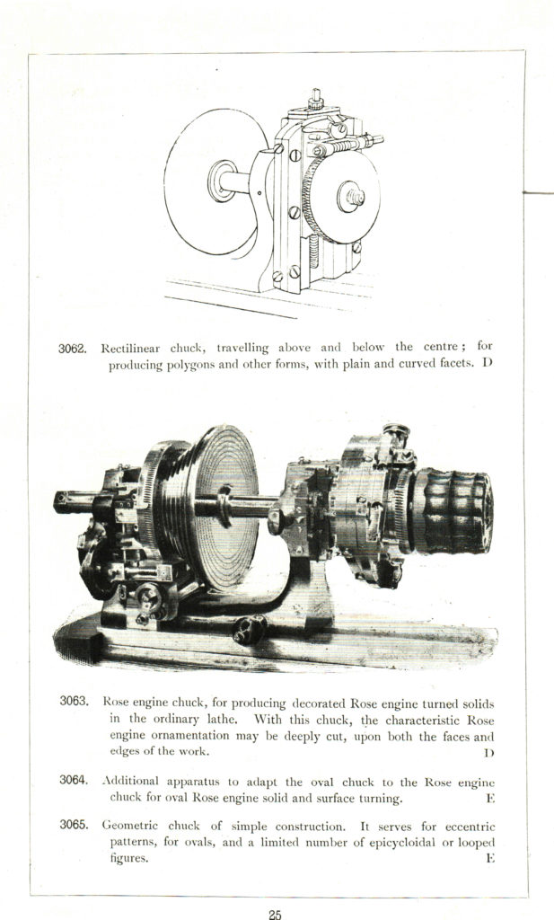
The Automatic Driving Apparatus appeared in the 1892 catalog; however, it was not named or given a part number. While researching for this article I inquired to the seemingly omniscient and ever helpful John Edwards who, as usual, quickly responded. He opened his letter thus, “I really have to reprimand you for not yet getting to Page 14 of my book (Holtz Vol VI); where it describes the AUTOMATIC DRIVING APPARATUS for use with the Rose Chuck (and other things).” However, John is a gracious man; and he went on to give a fuller explanation than his book offers. Here is an excerpt from his reply:
“The automatic Driving Apparatus can be driven very slowly (to produce a ‘mirror’ finish) from the overhead by one of the two pulleys on the tangent screw. William Gaddum used this lathe constantly and the tangent screw would have been one of the components subjected to the most wear. This is an ideal accessory to set running and then go off for a cup of tea, because it could either be set to rotate constantly or to make cylindrical, spiral or reciprocator patterns with the slide-rest using its automatic stop mechanism.
All this was worked out by George Budd from the simple SEGMENT STOP APPARATUS whereby you can insert two STOP pins in a pair of the 72 Segment divisions on the tangent wheel. This enables you to do by hand what the AUTO DRIVER does automatically. You will notice also that there are 2 kind-of brackets top and bottom of the AUTO DRIVER and if you put pins in 2 of the 72 Segment Holes, they will disengage the drive when struck. What a clever fellow was our George!”
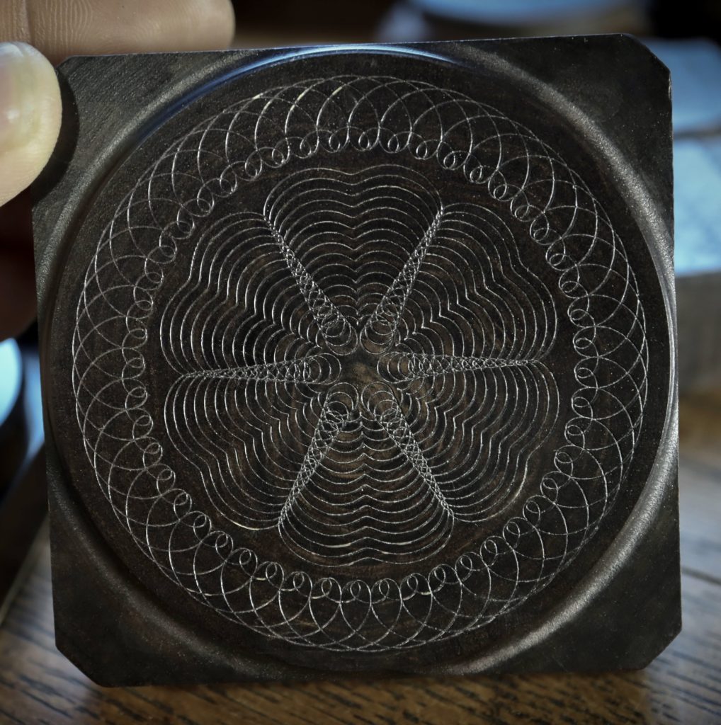
Gaddum, the owner of the lathe, is famous for having made and printed a large number of patterns in anticipation of producing a book that never materialized. One of his patterns is shown in African blackwood below.
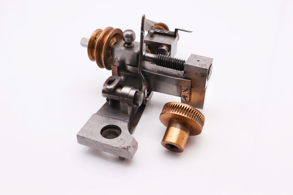
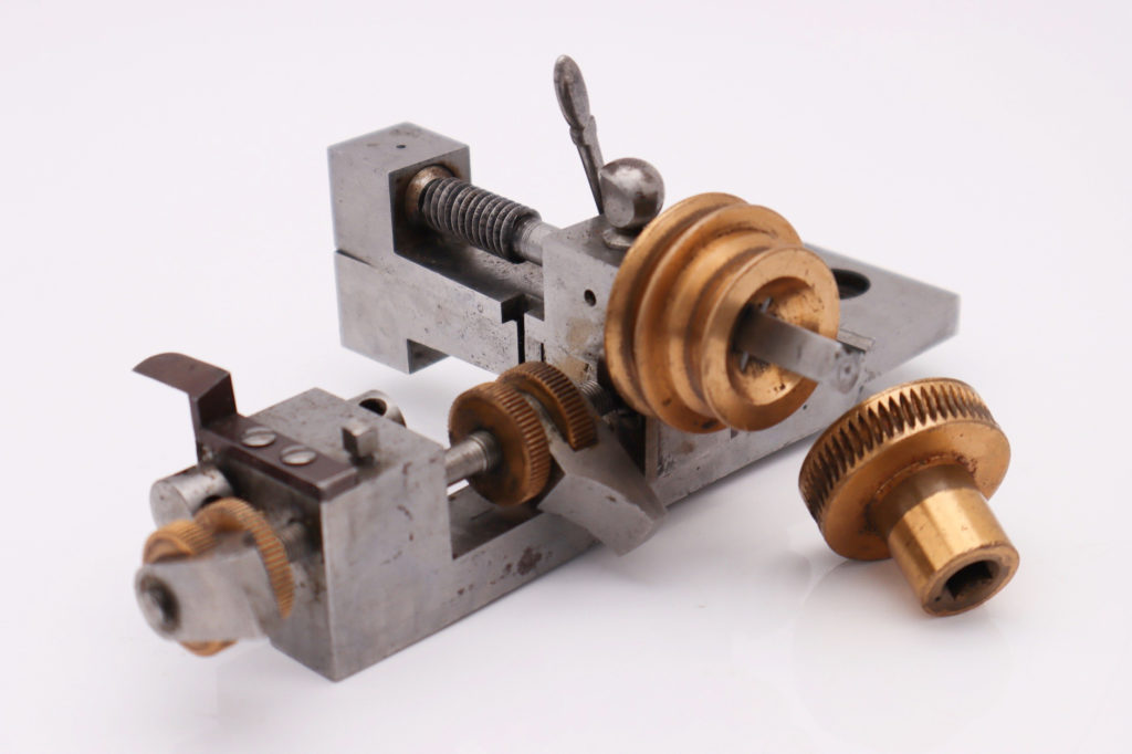
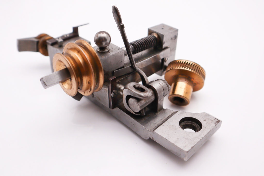
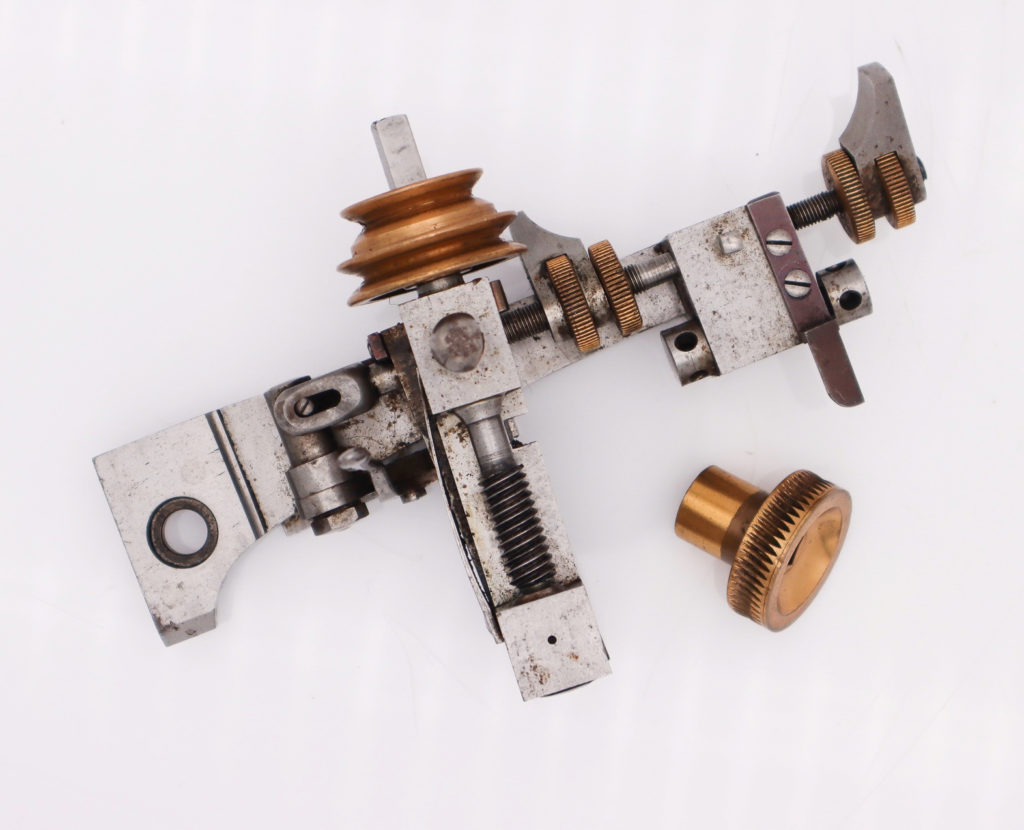
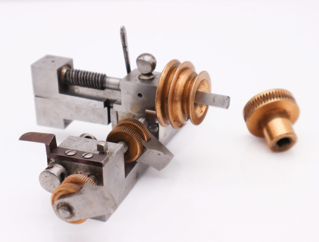
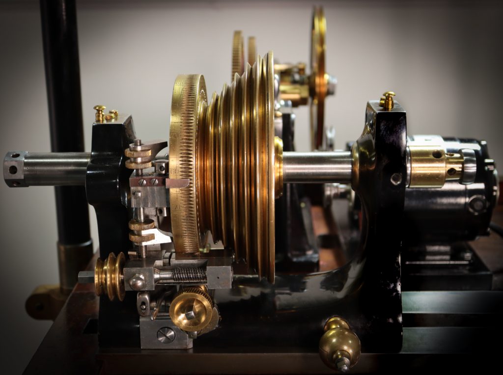
In the lower left area of the following picture, you can see the two-step pulley attached to the worm shaft described in John’s letter. The worm shaft mounting pivots vertically to engage and disengage the worm with the small worm wheel below it. The small worm wheel then turns the worm that drives the large headstock worm wheel. The main pulley on the headstock spindle is provided with holes on the outboard face (not visible in photo) which accept “segment stop pins.” If these pins are used with the Automatic Driving Apparatus, they can be used to trip the automatic stopping device described in John’s note.
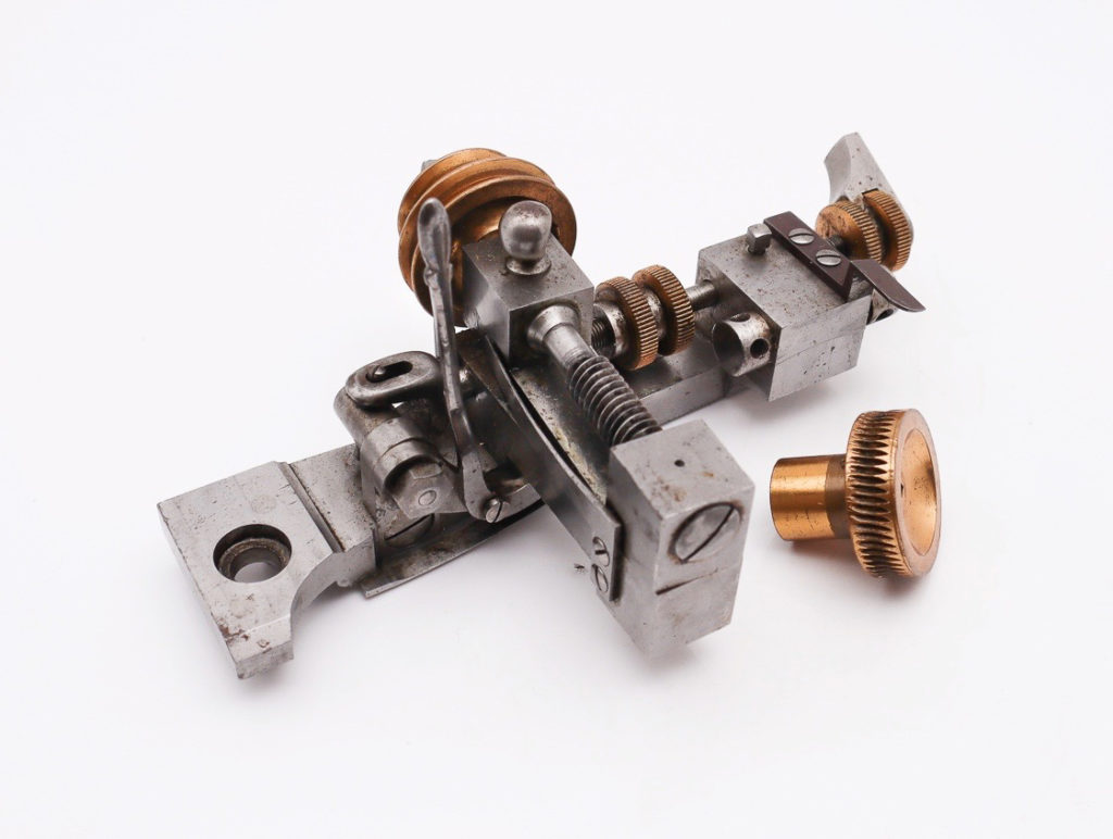
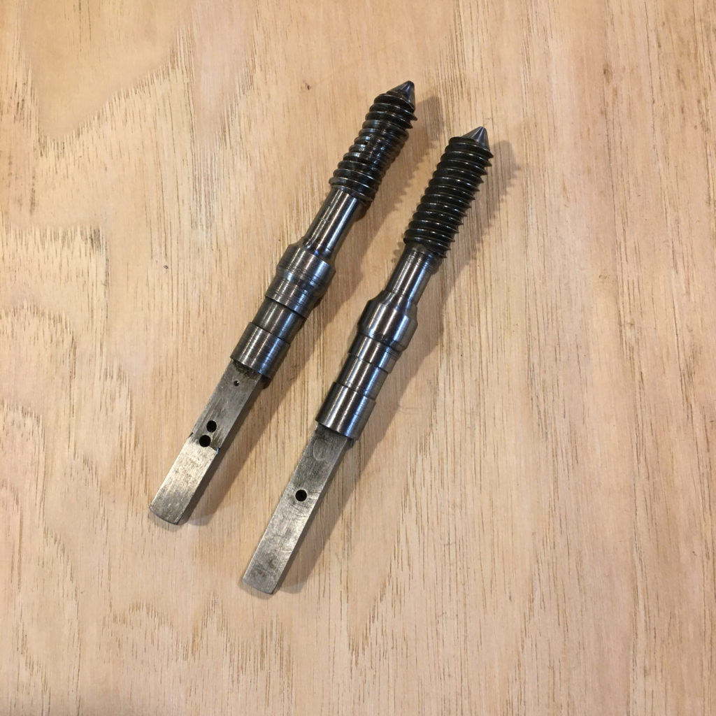
Our attention was directed to this topic because the worm on our device was badly worn. John was correct, it is the part most vulnerable to wear. Some might be surprised at this, as it’s quite counterintuitive. One would think that the softer material, brass, from which the worm wheel was made would wear first. There are two answers to this. First, the worm itself goes one full turn for every notch in the worm wheel, which means it sees a lot more friction over its small contact area. The other reason for it is that abrasives impregnate the softer material and act as a lap on the harder. In my observations as a clockmaker, steel pinions wear faster than brass gears, and, even more remarkably, hardened pinions often wear faster than softer ones. Note the pronounced wear in the central are of the worm on the left in the following photo.
Wanting the device to be fully functional, and not having time to remake the worm myself, I set Christian to the task, which he handled admirably. Typically, Holtzapffel pitches are not compatible with our conventional American lathes; however, in this case we were fortunate. At first, we were in a quandary as to how we were going to match the thread pitch, but quite quickly Christian noted it was a three-start thread. Once that was discovered it came to light that an imperial pitch was a close enough match.
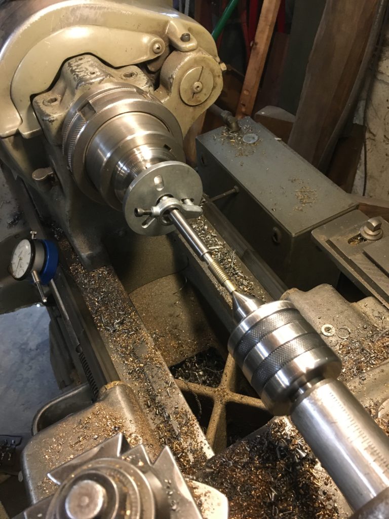
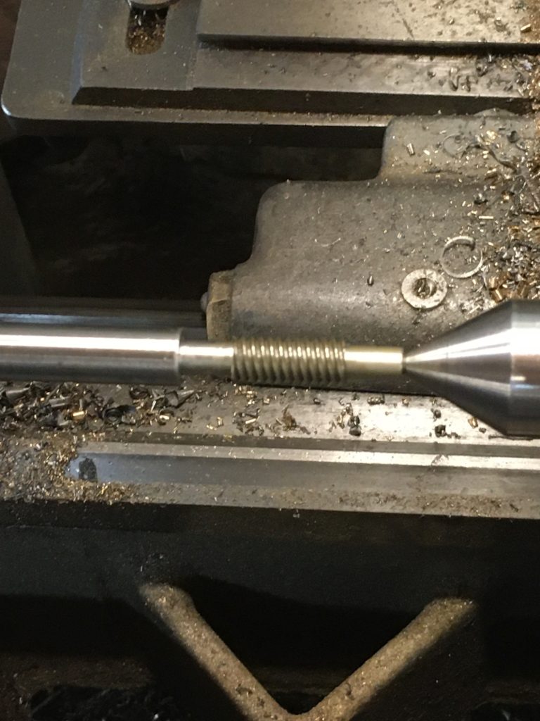
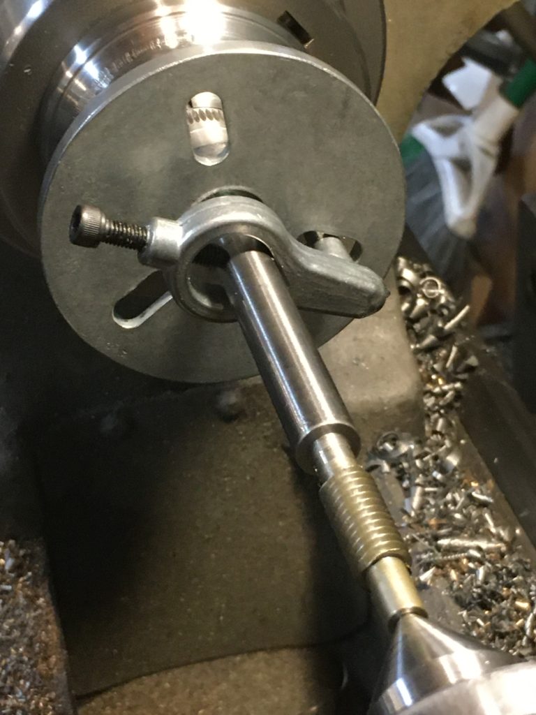
The next issue to be tackled was figuring out how to cut a three-start thread. I suggested the following set up which included the use of a Sherline index head spindle along with the faceplate, dog and driver that come with the index head as they supply it. Christian chucked the Sherline spindle into our South Bend and made quick work of the rest of the job. He simply used the three slots in the faceplate to place his three starts and turned it to the same depth.
After that, he hardened it and gave it a final finish that matches the rest of the tool.

The Automatic Driving Device is as beautiful as it is useful, and we’re quite glad to have it back up working and added to our bag of tricks.